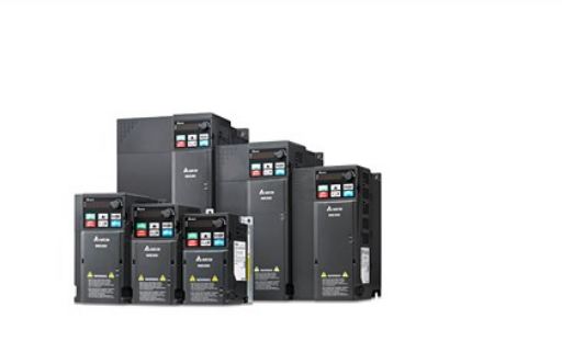
Delta frequency converter maintenance steps
Published:2022-12-29 17:13:21
First, the repair of frequency converter must first check whether the sound in the operation of the motor is abnormal, including whether it is sensational in the operation of the motor.
Two, check whether the natural environment of frequency converter installation is changed. For example, whether the operating temperature is normal. Those who know the maintenance of Delta frequency converter should understand that the operating temperature of frequency converter is generally prescribed in the range of -10℃ - +40℃, and 25℃ is appropriate.
Three, check the frequency converter heat exhaust fan is not normal operation, for example, the frequency converter heat exhaust safety channel is not smooth, there is also a frequency converter marked on the control panel to indicate the output of electricity flow, operating voltage and frequency of these various main parameters are not normal.
Four, frequency converter repair also need to check whether the frequency converter is high temperature. Infrared thermometer can be used to check whether the radiator of the converter is high temperature, or whether the odor is heavy. It is also necessary to check whether there are common fault alarms in the operation of the frequency converter.
Five, Delta frequency converter protection and maintenance should also ensure that the daily removal of the air inlet pipe screen inside the low-voltage complete equipment on time. Maintain control box and frequency converter in perfect condition for a long time. Because it can reasonably remove the area of dust on the frequency converter, but also prevent dust from entering the frequency converter, reasonably remove the oil stains of the frequency converter fan, and reduce the generation of heat discharge problems.
Delta DVP-1 22KW converter, no response on power-on, no display on actual operation control panel, 24V operating voltage of control terminal is 0. Common faults are identified as switching power supply circuit or switching power supply circuit supply system circuit. Check the energy storage capacitor at both ends of the DC circuit without 530V communication voltage.
Further check the circuit breaker FU of the pre-charging road has been broken, resulting in the switch power supply circuit can not get the input power supply, the whole machine strike. Fully consider the reason for the break is that the thyristor in the three-phase rectifier circuit is not triggered to break, and the pre-charging power supply circuit is subjected to the current impact, so as to break FU.
After the FU is replaced with a new one and energized, the communication voltage cannot be detected at the trigger terminals of the three thyristors. When a short contact is made with VT3 in the power supply circuit, the trigger terminals of the 3 thyristors all have the trigger operating voltage entered, and the 3 thyristors are switched on. Check VT3 collector junction has been open damaged, VT3 replaced with power tube BU406, the common fault lifted.
-
 202302-16
Solution of MCGS communication problem
1. How to check the communication status of the device in Kunlun Mode (MVGS)In all MCGS non-board devices (except some custom devices), *** channels are communication channels. That is, after entering···
-
 202304-21
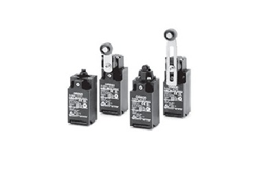
Fault detection methods for Omron relays
Fault detection Method One1. You can first check whether the voltage of the Omron relay is high or low. Generally, the maximum voltage is between 180V and 240V.Fault detection Method two2. In addition···
-
 202302-09
How to maintain MCGS touch screen
1. Wipe the phone screen with a dry cloth before opening it every day.2. Drinks or drops falling on the screen will cause the software to stop the reaction. This is because water droplets and fingers ···
-
 202212-29
Fault and maintenance method of MCGS touch screen
1. The fault of touch deviationIf the finger touches the position and the mouse arrow does not coincide. After installing the driver, you should not touch the center of the bull 's-eye vertically ···
-
 202303-01
The Siemens S7-1200 has three classifications of internal storage areas
The internal storage of the S7-1200 is divided into three types: working storage, loading storage and holding storage.Loading storage area:Non-volatile storage area. Used to store user project files (···


 +8618621383628
 +8613811814778
 info@zhongpingtech.com
 Building 26, Liyuan Community, Chaoyang District, Beijing, China