
Yaskawa servo drive debugging method steps
Published:2023-09-14 14:57:39
1. Basic wiring
The main power input is 220V, which is connected from L1 and L3 (the actual use should refer to the operation manual); Control power input r, t can also be directly connected - 220V; Motor wiring see page 22, 23 of the operation manual, encoder wiring see the operation manual, do not connect wrong.
Second, test steps
1.JOG test machine function Yaskawa servo can be tested only according to basic wiring; When the digital display is in the initial state 'r 0', press the 'SET' key, then press the 'MODE' key continuously until the digital display is' AF -- AcL ', then press the up and down keys to 'AF-JOG'; Press the 'SET' key to display 'JoG -' : press and hold the '^' key until 'rEAdy' is displayed; Hold down the '<' key until 'SrV-on' is displayed; Press and hold the '^' key to rotate the motor counterclockwise, press the 'V' motor to rotate clockwise, and its speed can be set by the parameter Pr57. Press 'SET' to end.
2. Yaskawa servo internal speed control mode COM+ (7-pin) is connected to +12 -- 24VDC,COM- (41-pin) is connected to the DC source; SRV -- ON (pin 29) connected with COM-; Parameter No.53 and No.05 should be set to 1: (Note that such parameters should be written into EEPROM after modification and re-powered) Adjust parameter No.53 to make the motor rotate. The parameter values are the rotational speed, with positive values for counter-clockwise rotation and negative values for clockwise rotation.
3. Yaskawa servo position control mode
COM+ (7-pin) is connected to +12 -- 24VDC, and COM- (41-pin) is connected to the DC power source; SRV -- ON (pin 29) is connected to COM-LUS1 (pin 3), SIGN1 (pin 5) is connected to the positive terminal of the pulse source (+5V); PLUS2 (pin 4) is connected to pulse signal, SIGN (pin 6) is connected to direction signal; Parameter No.02 is set to 0, No42 to 3, and No43 to 1. PLUS (4 pins) into the pulse signal, can make the motor rotation; Change SIGN2 to change the motor steering. In addition, adjusting parameters No.46 and No.4B can change the number of pulses required per revolution of the motor (that is, electronic gear).

-
 202307-20
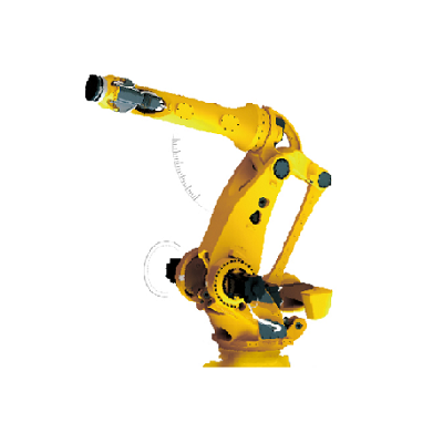
How to disassemble the five or six axes of the Eston robot?
1. Open the shell of the robot to reveal the motor base.2. Use a screwdriver or wrench to remove the screws on the motor base.3. Remove the screw, lift the motor base, and remove it from the robot.4. ···
-
 202302-16
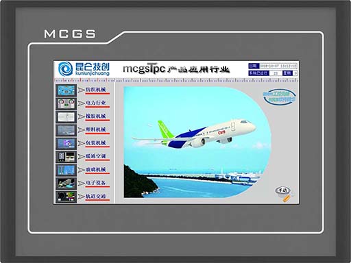
Mitsubishi 5U PLC and MCGS touch screen connection
First of all, let's look at the interface Settings of Kunlun touch screen.1. Click the device window to enter Add PLC2. Add a TCP parent serial port and add a 5U device below3. Double-click the pa···
-
 202307-07
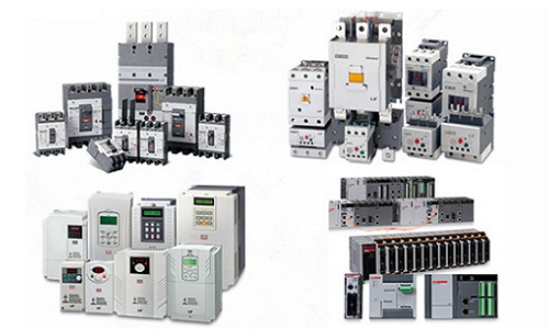
LS PLC use introduction
1, for switching quantity controlThe ability of PLC to control the switching quantity is very strong. The number of points controlled by the input and output points, as few as a dozen points, dozens o···
-
 202305-12
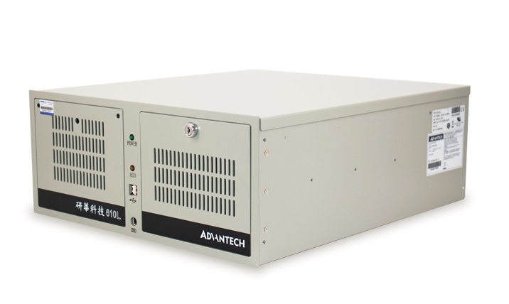
The hard disk light of Advantech industrial computer 610L is not on
Hard disk fault: The hard disk may be faulty, causing the hard disk indicator to be off. You can try to restart the computer. If it still does not light up, check whether the hard disk is recognized b···
-
 202212-30
What are the PLC characteristics of ABB?
1, high reliability, strong anti-interference abilityHigh reliability, strong anti-interference ability is one of the most important characteristics of PLC. The average trouble-free time of PLC can re···


 010-64225983
 +8613811814778
 info@zhongpingtech.com
 Building 26, Liyuan Community, Chaoyang District, Beijing, China