
Schneider frequency converter setup steps detailed
Published:2023-03-31 10:08:32
1. Macro Equipment:
According to the control requirements of different loads, Schneider inverter defines the macro equipment and the initial function of I/O terminals.
Change macro equipment, can be fixed under the "Brief startup menu".
If necessary, you can also re-equip the terminal definition separately, so that the macro is equipped with a custom macro for the user.
2. Set motor nameplate data
Set the best data about the motor: rated voltage, rated frequency, rated current, rated speed, power factor, etc., in the menu of "Brief Settings" or "Motor Control".
3. Motor self-tuning (self-learning)
After the motor nameplate data is set, the motor can be self-tuning (self-learning).
The detailed operation is as follows: enter the menu of "Brief Setting" or "Motor operation", enter the self-tuning (tUn) parameter, select "Request self-tuning (YES)", press "ENT", and the inverter will take the initiative to self-tune the motor. If the self-setting is successful, the screen will display "done"; otherwise, "no" will appear.
Note that self-tuning should be carried out in the absence of command activation.
4. Set maintenance parameters
Set maintenance parameters, such as CLI current limiting parameters in the Motor Control menu
Demand attention: When the power of the converter does not match the power of the motor, more attention should be paid to the maintenance parameters to avoid improper maintenance and damage to the equipment.
5. Define logical terminals according to control requirements
The function of the I/O terminal is already assigned when the macro is equipped. When these devices do not satisfy the control requirements, you can change the definition of the corresponding terminal in the I/O menu (display I_O).
I/O terminals can be defined as a variety of functions. Please refer to the ATV61 user manual for details.
6. Set general parameters according to process or load requirements
According to the detailed application situation, the parameters required to be set are generally in the "brief setting" menu or "Setting" menu, such as: acceleration time ACC, deceleration time DEC, low frequency LSP, high speed frequency HSP, etc.
For details, see the ATV61 User manual.
7. Test run, adjust the control parameters of frequency converter according to the running condition
After the above Settings are completed, the frequency converter can be started for trial operation.
The initial running time should be short, pay attention to check the direction of motor rotation.
If the motor steering is not correct, the PHr parameters can be corrected in the "Brief Settings" menu or the "Motor Control" menu.
According to the load operation condition, targeted adjustment of other parameters.
-
 202307-07
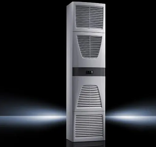
The alarm code cause and diagnosis method of the cabinet air conditioner of Rittal
Alarm code: A01System message: Open the cabinet doorAir conditioning cause: The opening and closing position is incorrectDiagnostic method: Check the transition position of the door and, if necessary,···
-
 202212-30
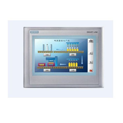
Siemens operating panel (HMI) order number complete
Siemens Operating Panel (HMI) order number complete - Siemens touch screen order number complete
-
 202302-10
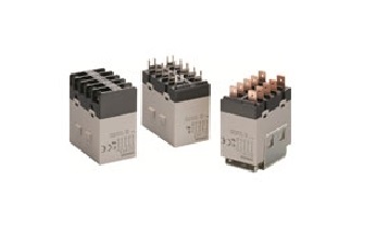
Parameter interpretation of Omron relay
Rated working voltage (current) :Also known as coil voltage, it refers to the voltage or current that the relay can work reliably. When the relay is working, the input voltage or current of the relay ···
-
 202301-11
What are the common faults of Advantech industrial computer?
1. Maintenance of chip-level motherboard, dealing with crash, startup without flash, power-off and other problems, and providing BGA service;2. Deal with the black screen and flower screen in the oper···
-
 202302-24
WEINVIEW touch screen common faults and maintenance
(1) The startup indicator is normal, but the display shows no signal input (black screen);(2) Press the on key, the host does not have any response (the indicator light is not bright, the host startup···


 +8618621383628
 +8613811814778
 info@zhongpingtech.com
 Building 26, Liyuan Community, Chaoyang District, Beijing, China