Mitsubishi inverter overload fault judgment method
Published:2023-02-02 14:41:50
1. Check whether the three-phase power of the motor is balanced
(1) If the three-phase voltage of the motor is not balanced, the three-phase voltage of the output end of the Mitsubishi inverter should be checked again.
(2) If the three-phase voltage of the Mitsubishi frequency converter is also unbalanced, the problem is in the Mitsubishi frequency converter. The inverter module and its driving part should be checked.
(3) If the voltage at the output end of the Mitsubishi frequency converter is balanced, the problem lies in the line between the Mitsubishi frequency converter and the motor. It should be checked whether all the screws at the terminal have been tightened.
(4) If there are touchers or other electrical appliances between the frequency converter and the motor, it is also necessary to check whether the terminals of the relevant electrical appliances have been tightened, and whether the touch condition of the contacts is outstanding.
(5) if the three-phase voltage of the motor is balanced, the working frequency of tripping should be understood;
(6) If the working frequency is low and there is no vector control (or no vector control in the frequency converter), the U/F ratio is mainly decreased;
(7) If the load can still be driven after falling, it means that the preset U/F ratio is too high, and the peak value of the excitation current is too large. The current can be reduced by decreasing the ratio of U/F;
(8) If the load is not moving after falling, the capacity of the frequency converter should be considered to increase;
If the cause is not found through the above view, it should be checked whether it is a mistake.
The way to judge is to measure the output current of Mitsubishi frequency converter with ammeter under light load or no load, and compare it with the running current value displayed on the display screen. If the current reading displayed on the display screen is much larger than the actual measured current, it indicates that the error of the current measurement part inside Mitsubishi frequency converter is large, and the "overload" trip may be wrong action.
2. Check whether the motor is overheating
(1) If the temperature of the motor is not high, the first thing to check is whether the electronic thermal maintenance function of the frequency converter is preset reasonably.
(2) If there is margin for Mitsubishi frequency converter, the preset value should be relaxed;
(3) If the allowable current of Mitsubishi frequency converter has no margin and can not be relaxed, and the overload is normal overload according to the field process requirements, it indicates that the choice of Mitsubishi frequency converter is not appropriate. The capacity of Mitsubishi frequency converter should be increased and a larger Mitsubishi frequency converter should be replaced.
-
 202305-19
Mitsubishi PLC control inverter method
First, Mitsubishi plc analog signal control frequency converterHardware: fx1n type, fx2n type plc host, equipped with a simple FX1N-1DA-BD extended analog output board; Or analog input/output mixed mo···
-
![[Gongboshi case] electric control cabinet box welding - Doctor of engineering independent brand to help customers intelligent upgrade production line](/static/upload/image/20221230/1672385439299376.png) 202212-30
202212-30[Gongboshi case] electric control cabinet box welding - Doctor of engineering independent brand to help customers intelligent upgrade production line
Welding of electric control cabinet cabinetIn this case, the welding robot is combined with the Doctor of engineering robot positioner and gun cleaning station to realize the automatic welding of the ···
-
 202212-29
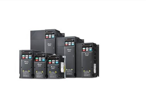
Delta frequency converter maintenance steps
First, the repair of frequency converter must first check whether the sound in the operation of the motor is abnormal, including whether it is sensational in the operation of the motor.Two, check whet···
-
 202303-01
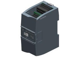
The Siemens S7-1200 has three classifications of internal storage areas
The internal storage of the S7-1200 is divided into three types: working storage, loading storage and holding storage.Loading storage area:Non-volatile storage area. Used to store user project files (···
-
 202302-16
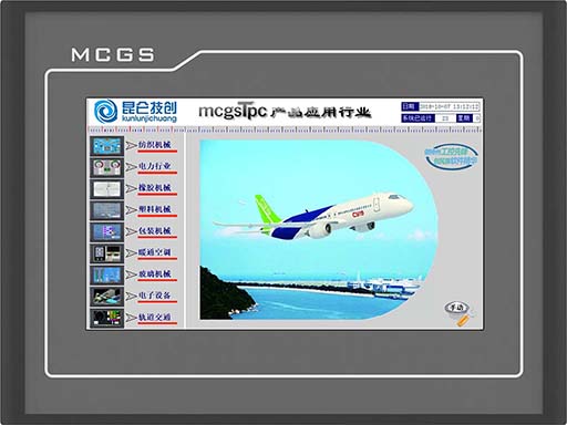
Mitsubishi 5U PLC and MCGS touch screen connection
First of all, let's look at the interface Settings of Kunlun touch screen.1. Click the device window to enter Add PLC2. Add a TCP parent serial port and add a 5U device below3. Double-click the pa···


 +8618621383628
 +8613811814778
 info@zhongpingtech.com
 Building 26, Liyuan Community, Chaoyang District, Beijing, China