
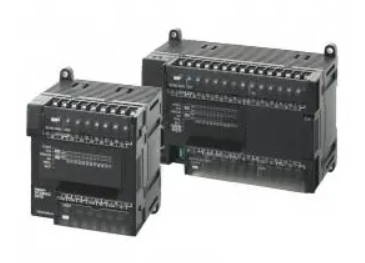
Omron CP1 series PLC interrupt classification
Published:2023-02-21 15:57:18
1. Direct I/O interrupt is a change in the interrupt input from the built-in input unit on the CPU rack (0→1; 1→0).
2, count interrupt, PLC CPU unit built-in input pulse count, count reach set value and execute interrupt.
3, timing interrupt, PLC CPU unit of the built-in timer to a certain time interval and the execution of the interrupt.
4, high speed counting interrupt, the CPU unit of PLC built-in high speed counter to the input pulse count, count to reach the set value, or through the area ratio and the execution of the interrupt.
5, external interrupt, CP1 series PLC and CJ or other series of high function I/O unit or CPU high function unit connection, if received the interrupt generated by these units, CP1 series PLC CPU unit will immediately respond to the interrupt, the execution of interrupt subroutine.
The priority of the five interrupts in descending order is: external interrupt > Direct I/O interrupt > Count interrupt > high-speed count interrupt > Timed interrupt.
In the same interrupt level, the task with a smaller number takes precedence over the task with a larger number.
-
 202302-14
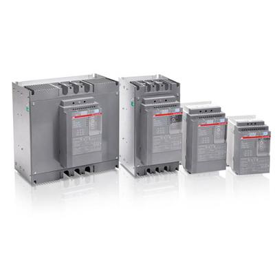
What fault does ABB soft starter show EF32?
What is ABB soft starter fault codes EF32.The ABB PSE series soft start is a three-phase controller with a compact design and a wide range of applications.It is mostly used in water pump motors,and th···
-
 202410-21
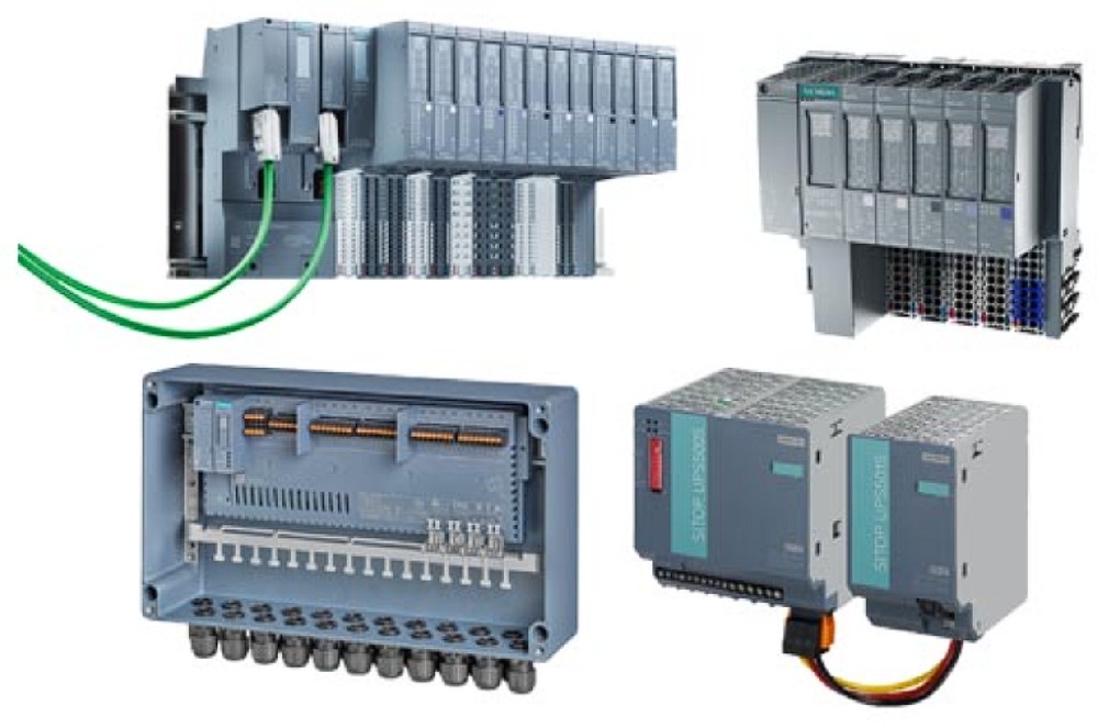
Input and Output Modules: Everything You Need to Know
I/O modules(input/output modules)manage the communication between the CPU and the network,including data transfer,power load management,and machine function control.It enables system integrators to co···
-
 202307-27
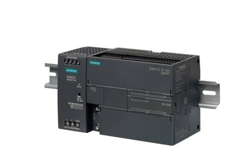
Siemens S7-200 SMART Common questions about serial communication
1. Does the S7-200 SMART support Modbus ASCII communication mode?STEP 7- The Micro/WIN SMART software does not provide the Modbus ASCII communication mode instruction library. If the S7-200 SMART CPU ···
-
 202301-06
Fault analysis and maintenance steps of WEINVIEW touch screen failure to turn on
1. The power cable is incorrectly connectedThis may seem obvious, but make sure the power cord is connected to the back of the touch screen and plugged into a power outlet. If it looks connected corre···
-
 202309-14
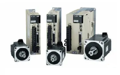
Yaskawa servo drive debugging method steps
1. Basic wiringThe main power input is 220V, which is connected from L1 and L3 (the actual use should refer to the operation manual); Control power input r, t can also be directly connected - 220V; Mo···


 +8618621383628
 +8613811814778
 info@zhongpingtech.com
 Building 26, Liyuan Community, Chaoyang District, Beijing, China